 Eng
Eng CN
CNCatalog
search products
online service
TEL: +86-731-28679679
FAX: +86-731-28679979
Mobile: +86 139 0733 7319
E-mail: info@hvr-magnet.com
![]()
TEL: +86-731-28679679
FAX: +86-731-28679979
Mobile: +86 139 0733 7319
E-mail: info@hvr-magnet.com
![]()
The electro-permanent lifting magnet controller consists of the control units, the control power conversion part, the status indicator indicating lamp, the remote control, the power switch, the button, the cable connectors and the junction box, etc. Each part is described as follows.
1. The control unit, number 6, maximum power:17KW;
The control unit to the input and the output interface is shown in figure 4;
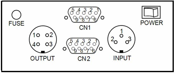
Among them:INPUT for the input interface,and the input voltage is AC380V, pin 1,pin2 connected with L1,L2 respectively;
OUTPUT output is the interface, the highest output voltage is DC170V, factory setting is DC140V, pin1 for the first road is positive output ,and pin2 for the second road is reverse output,pin3 is for the two public output.
CN1:the control extension interface;
CN2:the parameter setting interface,don’t change it;
FUSE:0.5A;
POWER:power switch
2. Air Switch:100A / 3P;Schneider
3. The control transformers:input=AC380V,Output =AC220V / 150W;
4. The switching power supply:AC220V / DC24V;
5. The big indicating lamp:DC24V / 5W,diameter 55mm,red/green/yellow color
7. The remote control:Yuting F21-10S (Made in Taiwan)
8. The fuse tube:5A;
9. The button and indicator:DC24V, diameter 22mm.
10. The intermediate relay:Schneider